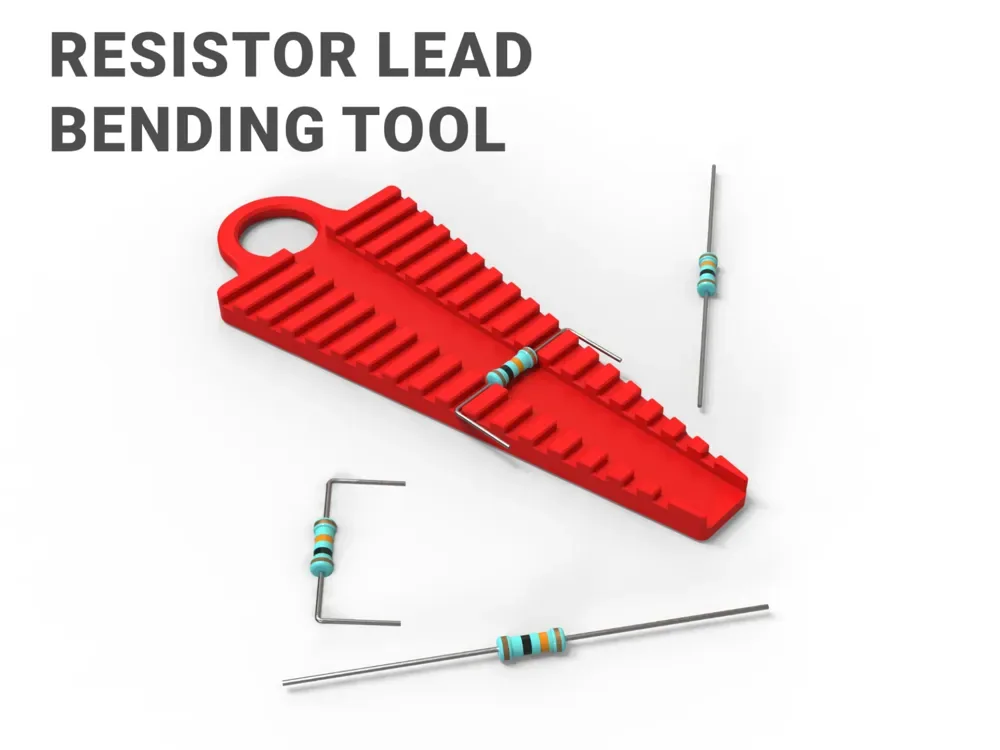
 Design reference photo
Creator photo; included parts are listed below. Accessories not included.
Resistor Lead Bending Guide — 63 mm Design
3D printed in PETG for forming component leads before assembly.
Shipping within Canada is included in the listed price. Applicable taxes are calculated at checkout. Secure checkout for Canadian shipping addresses. Choose your quantity on Stripe. Shipping to the U.S.? Contact us for a shipping quote before ordering. U.S. shipping is an additional charge.
Check fit before ordering ↓A closer look
3D printed in PETG for forming component leads before assembly. Includes one 6.3 cm design bending guide. Electronics, batteries, metal contacts, fasteners, accessories shown and installation are not included.
Check the fit
Start with these details so you can choose the right part for your setup.
- Confirm your board, connector or rack dimensions and mounting-hole pattern before ordering.
What’s included
- One 6.3 cm design bending guide.
- Electronics, batteries, metal contacts, fasteners, accessories shown and installation are not included.
Prepare leads before the board is crowded
A bending guide is most useful at the component preparation stage, while the board and resistor markings are easy to see. Sort the resistors for a small assembly step, identify the intended board positions, and compare their hole spacing before forming the leads. Working in small groups helps keep similar-looking values from becoming mixed after bending. The guide gives you a physical reference to return to when several components need the same arrangement. It is also useful for checking whether a proposed lead shape will sit comfortably before you commit to preparing a whole batch. Keep the circuit diagram or parts list beside the work area so the shaping step remains connected to the actual assembly plan.
Check the lead spacing you actually need
The 63 mm design name identifies this version of the guide; it does not establish a universal resistor size or a guaranteed spacing for every board. Compare the guide geometry with your component body, lead diameter, and required hole centres. The listed 29.42 × 76.8 × 4 mm measurements describe the printed part overall, rather than the spacing of each working feature. If a particular bend pitch matters, confirm that feature before ordering. Allow room for the component body and avoid trying to make a lead turn directly against its end. A sample formed lead should enter the intended holes without needing to be pulled sideways or pressed hard against the board.
Use a repeatable, gentle preparation routine
Work with loose, unpowered components and support each part while forming its leads. Make a controlled bend, check the result, and move on once the shape matches the assembly. Repeatedly straightening and rebending the same lead is a poor substitute for checking the spacing first. This PETG guide belongs with your preparation tools, away from the soldering iron tip and the hot work area. Brush away loose wire offcuts after the session so they do not interfere with the next component. Store the guide flat where another tool will not bend it. For repeated projects, retain a note of the board position and working feature you used, making the next preparation session easier to reproduce.
Product questions
What does the listed price include?
One 6.3 cm design bending guide. Shipping within Canada is included in the listed price. Applicable taxes are calculated at checkout. Electronics, batteries, metal contacts, fasteners, accessories shown and installation are not included.
Will this match everything shown in the photo?
The creator photo is a design reference and may show other variants, quantities or accessories. The included-parts list describes exactly what this listing supplies.
Can I use it for components other than resistors?
Possibly, when the body and leads suit the guide geometry. Compare a sample component and its required bend spacing first; the resistor-focused listing does not establish compatibility with every axial component or lead thickness.
Does it cut the leads to length?
No cutting function is described. Use the guide for lead forming, and treat lead trimming as a separate step determined by your board and assembly method. Keep sharp offcuts away from the guide and prepared components.
What should I send to confirm a specific bend?
Share the required hole-centre spacing, a component photo with a scale, and the component body and lead measurements. Those details are more useful than the resistor value alone when checking the physical forming arrangement.
Original design: OBE_Design — Resistor Lead Bending Tool - Leg Forming. MakerWorld model 1577635. Original design